Engineering Support - Aluminum Profile Specifications
The collective information below for our T-Slot framing profiles are the same tools our engineers use when evaluating stress and vibrations, and other material specifications for a given project. Going through these evaluations can be a confusing process, so please reach out to our engineering group anytime for assistance. Down-load ready catalog pdf pages containing all of this information are at the bottom of this page and each product page.
Additionally, on-line resource links (with CAD drawings and online calculation tools) are also available and which are located, by part number, at the bottom of each profiles page. For example: the online resources link for our SP3450N 28mm x 200mm framing profile will be located at the bottom of the 28mm framing profile page.
Aluminum Framing - Extruding Press Profiles
| Extruding Press Profiles | |
|---|---|
| alloy: | Al Mg Si 0.5 F 25 |
| material-№: | 3.3206.72 |
| condition: | hardened off by heat |
| (according to DIN EN 12020 part 2) | |
*Slide table to the left to see more data
Aluminum Framing - Surface Treatment
| Profile Surface Treatment | |
|---|---|
| anodized to: | E6 / EV1 (natural) |
| E6 / EV1 (black) | |
| coating thickness | ca. 15 µm |
| coating hardness | 250 - 350 HV |
| RAL colors powder coated (on request) | |
*Slide table to the left to see more data
Aluminum Framing - Mechanical Data
| Mechanical Data - T-Slot Framing Profiles | |
|---|---|
| tensile strength Rm: | min. 245 N / mm2 |
| elastic limit Rp 0.2: | min. 195 N / mm2 |
| ductile yield: | min 10% |
| modulus of elasticity | 70 kN / mm2 |
| Brinell hardness | HB 75 |
| thermal expansion | |
| 20 - 100°C: | 23.4 • 10-6 / °C |
| density: | 2.7kg / dm3 |
| (values in direction of press) | |
*Slide table to the left to see more data
Aluminum Framing - Profile Tolerances
Production related deviations in regards to straightness, flatness and twist but also outside and T-Slot dimensions are in accordance with the standard DIN EN 12020: 9001 (part 2).
Please Note – Paletti USA stocks the natural anodized finish in all sizes, the black anodized finish in select sizes. Other finish colors or un-finished framing profiles are available via special order.
Aluminum Framing - Supplied Lengths
Per DIN EN 12020 (part 2) - Requirements for exact extrusion lengths should be communicated with your order. Standard 3 m or 6 m length extrusions may be slightly longer due to production related requirements.
Aluminum Framing – NV Profile T-Slot
The NV t-slot is not pre-tensioned. The NV profile range has been designed for use with gauge plates and linear bearings that require the profile surface to be flat. For example: Jigs, fixtures, and special purpose machines.
Aluminum Framing – T-Slot Dimension Tolerances
The standard, semi, and superlight series framing profiles possess a standardised T-Slot shape. This guarantees that all fasteners and accessories can be utilised with the different profile series and sizes. T-Slot dimensions for 1” profiles are the same as our 20mm Series. T-Slot dimensions for 1 ½” profiles are the same as our 40mm Series. T-Slot dimensions on our 45mm and 50mm profiles are shown on their respective pages.

| Gauge | 20mm Series | 30mm Series | 40mm Series |
|---|---|---|---|
| a | 5.20 ± 0.1 | 8.20 ± 0.1 | 8.20 ± 0.1 |
| b | 11.50 ± 0.3 | 19.60 ± 0.1 | 20.00 ± 0.1 |
| c | 6.35 ± 0.2 | 10.10 ± 0.2 | 12.40 ± 0.2 |
| d | 1.80 ± 0.1 | 2.50 ± 0.1 | 4.50 ± 0.1 |
| e | 0.15 ± 0.1 | 0.18 ± 0.1 | 0.20 ± 0.1 |
*Slide table to the left to see more data
Aluminum Framing – Center-Hole Dimension Tolerances
The center-hole bore of the T-Slot framing profiles can be opened up according to the table. Profiles of the series superlight (40 mm) and midi (30 mm), however, may not be opened up due to the wall section around the center hole.

| 20mm Series | 30mm Series | 40mm Series | |
|---|---|---|---|
| drilling d1 | ø 4.3 - 0.2mm (M5) | ø 6.8 - 0.2mm (M 8) | ø 6.8 - 0.2mm (M 8) |
| drillable up to max. d2 | ø 6 mm (M 6) | - | ø 13 mm (M 12) (not for sl) |
*Slide table to the left to see more data
Aluminum Framing – Drilling Position Tolerances
The drilling position tolerance is dependent upon the number of the T-Slot center-hole bores and the contour of the profile.

| Profiles with open T-Slots | Profiles with closed T-Slots | ||
|---|---|---|---|
| Number of drillings | Z [mm] | Number of drillings | Z [mm] |
| 1 | 0.4 | 1 | 0.6 |
| 2 to 4 | 0.6 | >1 | 0.8 |
| >4 | 0.8 | - | - |
*Slide table to the left to see more data
Aluminum Framing – T-Slot Strength
Information in regards to the maximum allowable t-slot load capability F. These values already contain a safety factor (S > 2) against plastic deformation.

| Frame Type | Maximum pull charge F | Series Matrix |
|---|---|---|
| Standard | 5000 N | 40 |
| Semi | 2500 N | 40 |
| SuperLight | 1750 N | 40 |
| Midi | 750 N | 30 |
| Mini | 500 N | 20 |
*Slide table to the left to see more data
Please Note - Center-hole, drilling positions, and T-Slot Strength information for our 1” and 1 ½” profiles match their respective metric counterparts as explained in the T-Slot Dimension Tolerances explanation.
Deflection Calculation Examples and Formulas
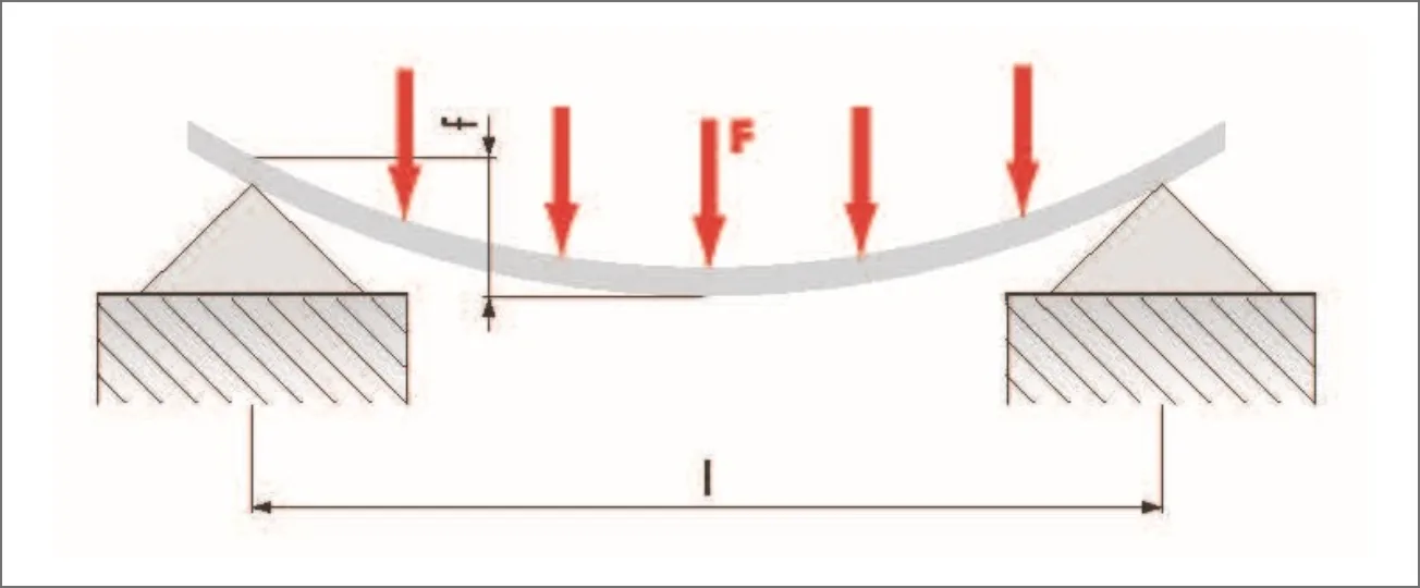
Deflection formula example – Two Stilts-Distributed Load – where the load might be temporary or incidental:

Deflection formula example – One Side Fixed-Point Load – where the load might be temporary or incidental:
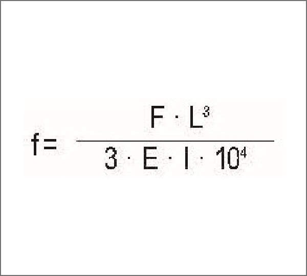
Deflection formula example – One Side Fixed-Point Load – where the load is dead weight:


Deflection formula example – Two Stilts-Point Load – where the load might be temporary or incidental:
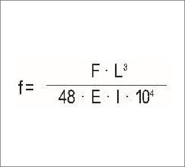
Deflection formula example – Two Stilts-Point Load – where the load is dead weight:


Deflection formula example – Two Sides Fixed-Point Load – where the load might be temporary or incidental:
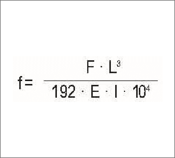
Deflection formula example – Two Sides Fixed-Point Load – where the load is dead weight:
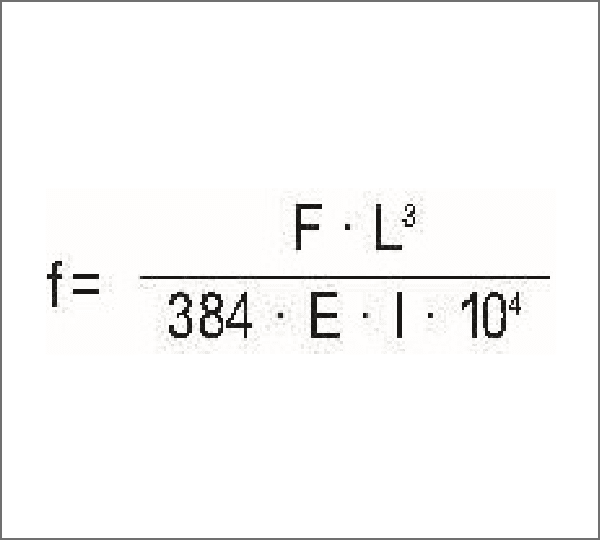

Please Note that in all the above stress / deflection calculation formulas the following definitions apply where:
F = load (N)
L = profile length (mm)
I = Inertia Moment (cm4)
E = Elasticity Modulus (N/mm2) EAI = 70,000 N/mm2
The following formula should be used when calculating “Control of the Deflection” where:
S = deflection (N/mm2)
Mb = maximum bending [N/mm]
W = resistive moment (cm3)

We invite you to review the on-line resources below, and please contact us for help anytime.
Please Note – contents shown by clicking on the below on-line resources will open in a new browser window. When you are done reviewing those contents, simply close that window to continue with this page.
Catalog page PDFs:
As noted above online resource links for each aluminum framing profile are listed by part number at the bottom of that individual profiles website page. All 16mm framing profiles are grouped together on the same page, and all 120mm framing profiles are grouped together on the same page. Etc…